
![]()
SuDS-related links
Keeping ahead
with SuDS
Attend SuDS training to keep ahead of the competition and to deliver innovative solutions in line with recognised good practice.
home > using SuDS > case studies >london 2012 olympic park
The London 2012 Olympic Park, Stratford, East London is situated on the River Lea and is generally bounded by the River Lee Navigation to the West, Westfield, Stratford City to the east, to the north by the A106 Eastway and to the south by the A11 Stratford High Street. This Case Study describes the features of the north of the London 2012 Olympic & Paralympic Park
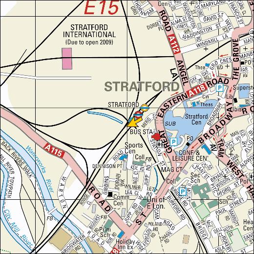
Figure 1 – London 2012 Olympic location
The Olympic development covers an area approximately of 250 hectares and when complete will house the Olympic Stadium, Aquatics Centre, Velodrome, Copper Box, BMX Track, Eton Manor and Riverbank Arena together with Sponsors Hospitality, the International Broadcast Centre/Main Press Centre Complex, the Orbit Tower, extensive public access areas (landscaped & paved), transport malls and operational facilities.
The site was formerly industrial/commercial development together with Lea Valley Park and was a known depository for building rubble from properties demolished during the Second World War. The site was known to be contaminated throughout and overlays the River Terrace Gravel and Chalk aquifers. Following completion of Enabling Works and remediation, the site will still contain significant areas of residual contamination. The figure below qualitatively depicts the expected level of residual ground contamination following remediation.
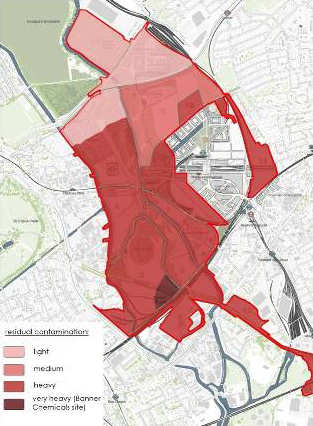
Figure 2 – Anticipated residual level of contamination post remediation works
This limited the opportunity for employing infiltration drainage systems across the site. A number of strategic watercourses traverse the Park, these being:
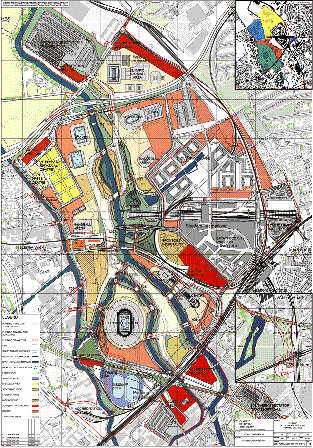
Figure 3 – Masterplan of Olympic & Paralympic Park (games phase)
The Park is protected against fluvial flooding and actively manages flooding generated by a 100 year return period rainfall event plus Climate Change allowance. Furthermore, the fluvial peak within the River Lea catchment was approximately 24 hours after a rainfall event and in negotiation with the Environment Agency and British Waterways it was agreed that surface water runoff generated should be collected and discharged to the watercourses in advance of the river peak flow.
The site topography was dramatically changed during the course of the development with some areas of the Park being raised in the order of 9m. Similarly forming the wetland bowl within the River Lea required significant widening of the river channel reducing existing levels to suit. Plateaus have been formed for the venues and associated facilities above the river flood level with access routes to towpath level (4.5m AOD) adjacent to the watercourse. The figure below shows the proposed topography scheme for the Park covering both Games and Legacy phases.
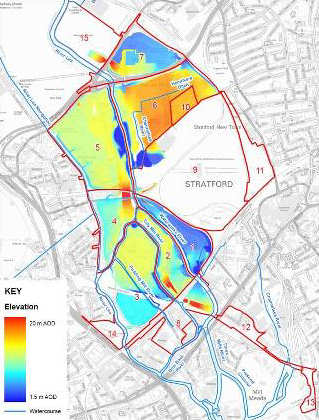
Figure 4 –Olympic & legacy topography scheme
Following completion of the Games the Park is to be transformed into the Queen Elizabeth II Olympic Park to form a mixed use development and significant landscaped area together with a number of retained venues converted for legacy usage.
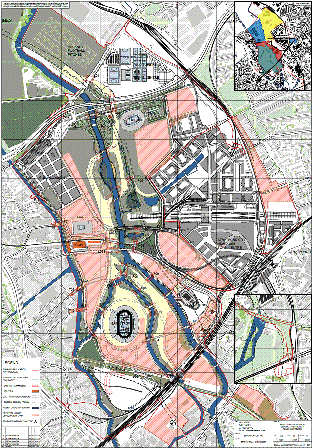
Figure 6 – Masterplan of Olympic & Paralympic Park (legacy phase)
This case study details the SuDS approach specifically implemented within Areas 5, 6, 7, 10 & 15 as detailed within Figure 4. Although the methods described below were consistent throughout the development.
Porous asphalt strips are extensively employed throughout the pedestrian concourse area of the Park. These strips act as collection systems for overland runoff generated and convey waters into granular trenches below the strips which contain perforated pipes. The perforated pipes drain to catchpits and thence into the spine network system into watercourses.
Within the wetlands area located adjacent to the Basketball Arena/Velodrome and Riverbank Arena further SuDS components have been employed that include swales, filter strips/drains and small volume balancing ponds.
Finally, rainwater harvesting has been installed at two permanent venues; Velodrome and Copper Box.
The loop road network together with spine surface water sewers and outfall structures was installed in advance of the design for the landscaping areas and venues. The design standards adopted for surface water drainage (SWD) were outlined within the Olympic Park SWD Technical Design Strategy, a requirement of which was to ensure all assets installed were adoptable by an appropriate authority. In line with this strategy and the requirement to discharge flows from the Park in advance of the fluvial peak in the River Lea, the spine networks were designed and installed as carrier pipes and manholes adoptable by Thames Water or Local Highway Authority and were sized accordingly.
Within the highways of the Park, traditional road gullies and combined kerb drainage collection systems were used. In addition, accreditation areas, back of house operational areas and transport malls were afforded similar systems supported by linear drainage channels.
The public access areas and landscaped regions provided greater opportunity to incorporate SuDS components focussing on water quality and amenity/diversity parameters.
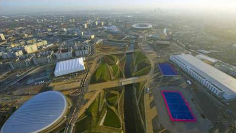
Figure 7 – Photograph of Park taken looking South
(Note - concourse shown by black/gold banding)
It was intended that the north park wetland feature will form a wildlife haven for plants and animals with habitats created for otters, kingfishers, grey herons and water voles.
Runoff generated within the public access paved areas of the Park is collected by the porous asphalt strips.
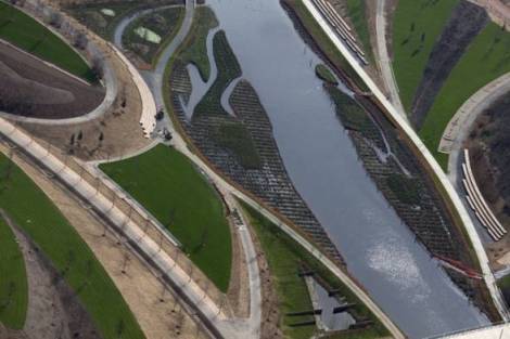
Figure 8 – Overhead photograph of wetlands during construction
Filter strips/drains were installed adjacent to the wetland pathways to treat and capture runoff generated. The collected waters were discharged through catchpits into downstream networks ultimately outfalling into adjacent watercourses. Within the soft landscape areas the filter drains were generally formed from a new product-tomarket manufactured from recycled thermoplastic material. The material was selected following a review of previous successful high profile installations and independent testing assessment the manufacture of the product was accredited as being carbon positive.
Swales are included within the wetlands area as conveyance devices. The swales incorporate check dams at intervals to reduce velocities and provide open water features alongside wetland pathways. Swales located west of the River Lea convey flows from the upper concourse to the river towpath level transmitting waters to an outfall structure.
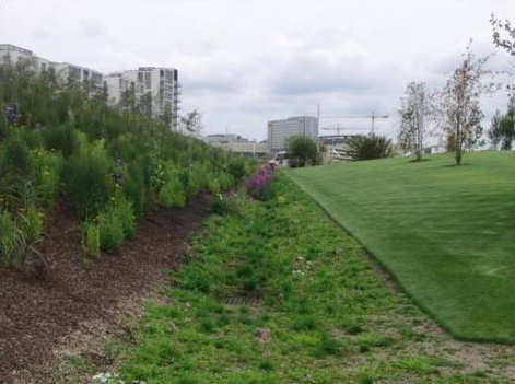
Figure 9 – Photograph along planted swale
On the east of the watercourse, the swales deliver runoff again from high to low level but discharge into habitat ponds and a wet woodland area adjacent to the River Lea. These habitat ponds and wet woodlands act as attenuation ponds installed with weirs limiting outflows whilst maintaining a minimum depth of water. Details of the above features are shown within figures 10, 11 and 12 below.
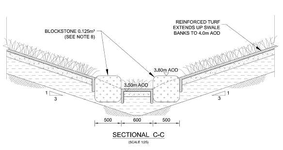
Figure 10 – Cross Section through swale & check dam
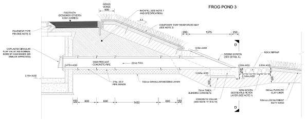
Figure 11 – Cross Section through habitat pond outlet
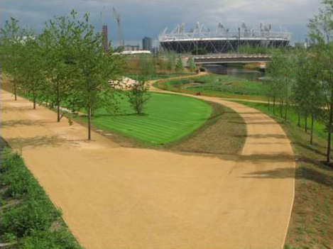
Figure 12 – Competed wetland area photograph
Surface Water Drainage systems designed and installed within the north park take account of criteria requirements agreed with Environment Agency as detailed below:
The following challenges were overcome during the project:
A number of internal and external stakeholders contributed to the design and implementation of the SWD systems within the Park and these are listed below:
This document has been compiled by the ODA Delivery Partner Surface Water Drainage (SWD) Coordinator (Barry Plowright – Senior Engineer, Atkins) author of the SWD Technical Design